ISSC/Kanson Electronics offers sensors manufactured using the latest electronic technology to create the highest levels of reliability, repeatability, durability and miniaturization. The impermeable resin filled casing makes these sensors particularly suitable for operation in very harsh environments.
According to the operating principle, electronic proximity sensors can be divided into the following categories:
- inductive
- capacitive
- photoelectric
- magnetic effect
Another classification based on the output stage can be proposed:
- DC self-amplified ON-OFF
- AC self-amplified ON-OFF
- NAMUR non-amplified
- analog with current output
- analog with voltage output
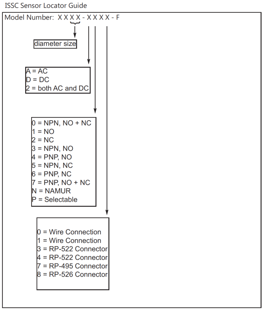
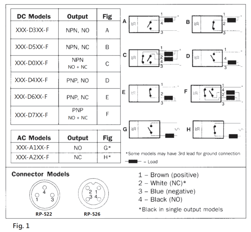
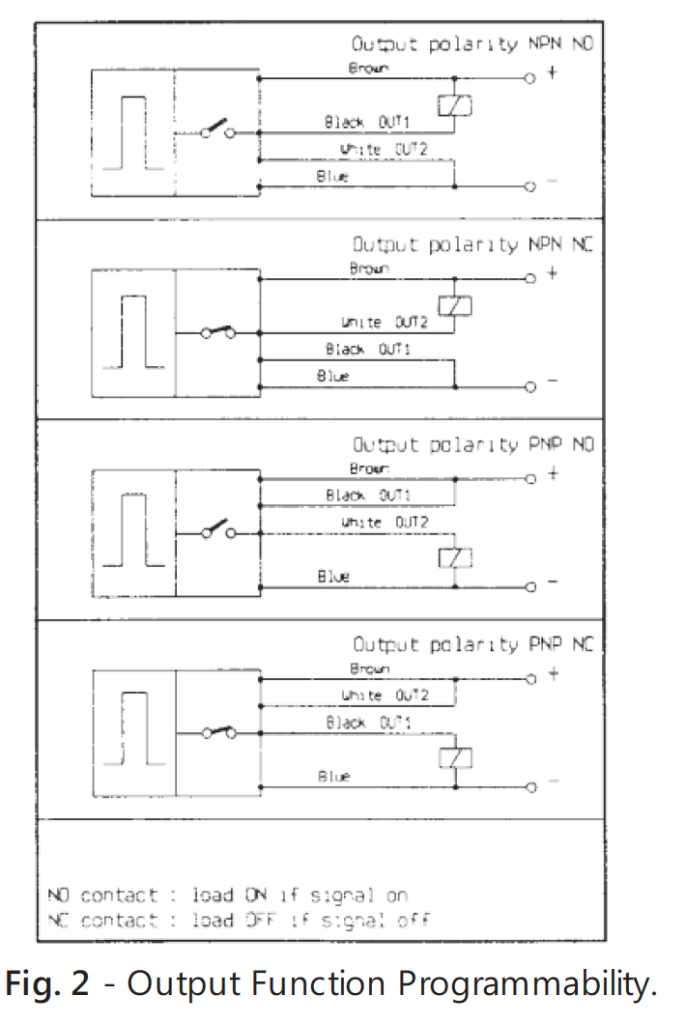
The ON-OFF models can have output polarity NPN or PNP and three different output functions: normally open (NO), normally closed (NC) and complementary (Fig. 1).
Some models implement the output function programmability idea: based on how signal wires connect to the load, all four PNP, NPN, NC and NO output function combinations are available (Fig. 2). ISSC electronic sensors are tested for shock resistance according to the IEC 68.2.27 standard; vibration resistance testing according to the IEC 68.2.6 standard. The number of operations is virtually unlimited. The values reported by this catalog are measured in accordance with CENELEC EN 50010 standards at a 20°C temperature.
INDUCTIVE PROXIMITY SENSORS
Inductive proximity sensors are suitable for the detection of metallic elements. The operating principle is based on a high frequency oscillator able to create an electromagnetic field in the close surroundings of the sensor. The presence of a metallic object (actuator) in the operating area causes a decrease of the oscillation amplitude. This happens when part of the electromagnetic energy that is transferred from the sensor to the actuator is dissipated by the effect of the Eddy currents (Focault Parasitic currents). The oscillation amplitude, therefore, decreases in accordance with the distance between the actuator and the sensor. This provides the sensor with analogic information about the object position (analog sensors) or can be turned, using a threshold circuit, into a digital signal (ON-OFF sensors).
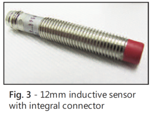
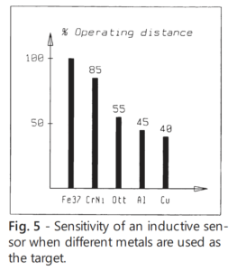
The accuracy of the sensor depends on the actuator shape and size and is strictly linked to the nature of the metal (Fig. 5). The cases of the inductive proximity sensors can be a metallic cylindrical, plastic or metallic rectangular, or plastic slot.
CAPACITIVE PROXIMITY SENSORS
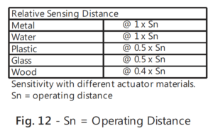
Capacitive proximity sensors make use of the variation of the parasitic capacity that develops between the sensor and the object to be detected. When the object is at a pre-determined distance from the sensitive side of the sensor, an electronic circuit inside the sensor begins to oscillate. The rise or the fall of such oscillation is identified by a threshold detector that drives an amplifier for the operation of an external load. A capacitive sensor can detect metallic and non-metallic objects (wood, plastic, liquid materials, etc.). The operating distance can be trimmed, making the sensor useful for each specific application. Capacitive proximity sensors are housed in smooth or threaded cylindrical metallic cases.
PHOTOELECTRIC PROXIMITY SENSORS
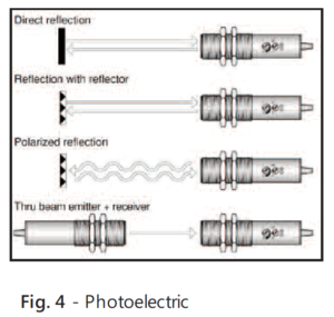
Photoelectric proximity sensors use physical properties of light sensitive elements, changing their electrical features according to light intensity.
The light intensity variation striking the receiver depends upon the presence or absence of the object to detect. This creates an electrical signal that, properly elaborated, activates a final amplifying stage that is capable of driving an external load. In order to produce correct operation up to 2.000 LUX of ambient light and to obtain high operating distances with low energy consumption, the transmitted light beam used is a modulated infrared type.
The photoelectric sensors can be divided into the following types:
-
Diffused sensors
- Diffused sensors use the reflected light of the object for detection leading it to the receiver. Transmitter and receiver are housed in the same case together with the electronic control circuits.
-
Reflex sensors
- Reflex sensors (Fig. 4) base their operating principle on the fact that the target stops the light beam emitted from the transmitter which is then reflected, by a reflector, to the receiver. Transmitter and receiver are housed in the same case together with the electronic control circuits.
-
Thrubeam sensors
- As the reflex type, thrubeam sensors use the interruption, caused by the target of the beam emitted from the transmitter and normally directed to the receiver by an optical system. The thrubeam sensors use components in separate housings.
MAGNETIC EFFECT ELECTRONIC PROXIMITY SENSORS
The magnetic effect electronic sensors uses a physical property called Hall effect. When a thin sheet of a semiconductor material (Hall element) is placed in a magnetic field and a perpendicular current is passed through it, a voltage is generated between the opposite borders of the semiconductor sheet.
The sensor is housed in a three branch slot case. The Hall element with all the electronics is in one branch and a magnet is in another branch. The third slot contains a ferromagnetic vane (actuator) that blocks the influence of the magnetic field of the Hall element, determining an output change of the state.
The case for the magnetic effect electronic sensor is made of plastic and strengthened with glass fibers.
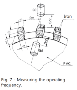
OPERATING FREQUENCY FOR INDUCTIVE & CAPACITIVE
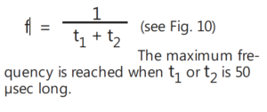
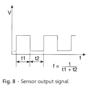
According to CENELEC EN 50010, this parameter is measured by the dynamic method shown in fig. 7 with the sensor in position (a) and (b). S is the nominal operating distance. The frequency is given by the formula:
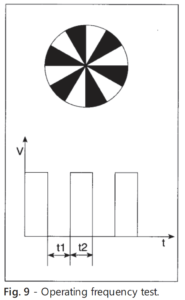
WORKING FREQUENCY FOR PHOTOELECTRIC SENSORS
The working frequency indicates the sensor switching frequency in time. The above parameter can be measured by using a wheel with alternating black and white sectors as a target (Fig. 9).
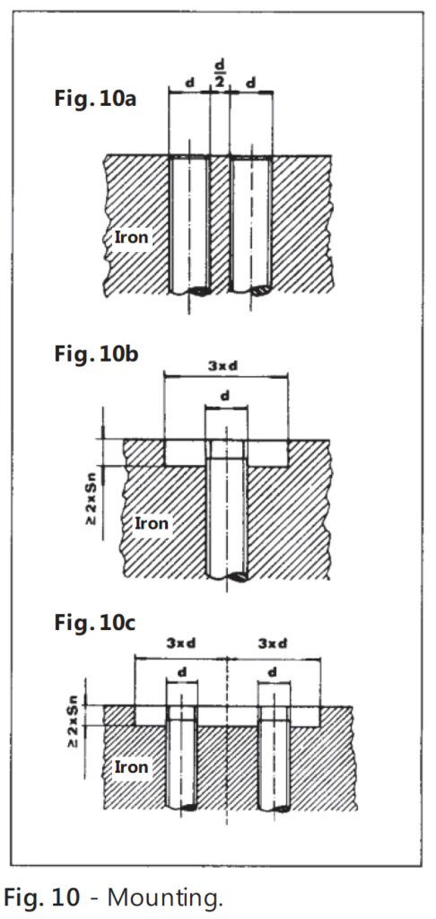
MOUNTING
Totally shielded models can be embedded in metal for flush mounting. For side by side mounting, refer to Fig. 10a. Partially shielded models should be mounted as shown in Fig. 10b. For side by side mounting of partially shielded models, refer to Fig. 10c.
DEGREE OF PROTECTION
Enclosure degree of protection according to IEC (International Electrotechnical Commission) is as follows:
- IP 65: Dust tight. Protection against water jets.
- IP 67: Dust tight. Protection against the effects of immersion.
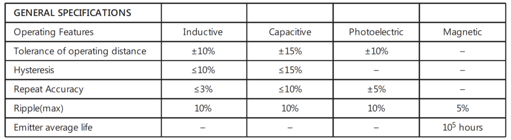
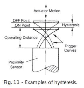
- Hysteresis: The distance between the “switching on” point of the actuator approach and the “switching off” point of the actuator retreat. This distance reduces false triggering. Its value is given as a percent of the operating distance or a distance. See figure 11.
- Repeat accuracy: The variation between any value of operating distance measured in an 8 hour period at a temperature between 15°C – 30°C and a supply voltage with a < 5% deviation.
- Ripple (max.): This is the maximum ratio percentage between the residual AC voltage (ripple, peak to peak) on the DC supply voltage and the DC supply itself that the sensor will operate on.